Solar container liquid cooling system working principle diagram explanation picture
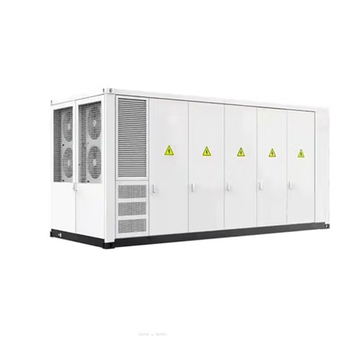
Liquid Cooling Container Energy Storage System Design Drawings
Meanwhile, the nuclear-grade 1500V 3.2MW centralized energy storage converter integration system and the 3.44MWh liquid cooling battery container (IP67) are resistant to harsh environments such as
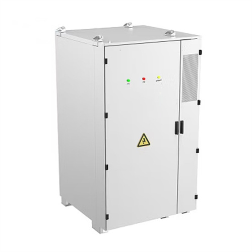
MTCB-Liquid Cooling 215Kwh 430Kwh 645Kwh 699Kwh Continer
The liquid cooling system ensures higher system efficiency and cell cycling up to 10,000 cycles. The liquid cooling system reduces system energy consumption by 20% and extends battery life by 10%.
Water Cooling Explained: How It Works and What Parts You Need
Video explanation and diagram of how liquid cooling works, as well as a list of what parts you need to build a water cooled PC.more Audio tracks for some languages were automatically generated.
Energy storage liquid cooling system working principle diagram
system comprises of liquid cooling plates (LCP) and suited liquid-cooling network. In its design, two primary cha lenges must be addressed to achieve the thermal management target mentioned above.

Related Contents
- Grid solar container working principle diagram explanation
- Base station solar container working principle diagram explanation
- Video of the working principle of solar container liquid cooling unit
- Working principle of water pump in liquid cooling system of solar container power station
- Working principle of solar container liquid cooling pipe system
- The complete design scheme of solar container liquid cooling working principle
- Solar container power station working principle diagram explanation
- Solar container battery working principle diagram explanation
- Working principle of solar container liquid constant temperature system
- Deceleration solar container motor principle diagram explanation
- Solar container liquid cooling system diagram
- Methanol solar container working principle picture