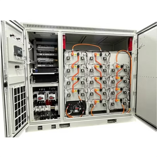
Chemical solar container application example diagram

Exploring Chemical Solar Cells: A Comprehensive Analytical Guide
The following diagram provides a conceptual overview of the layered structure within a typical chemical solar cell. Although not a visual image, this scheme offers a clear textual illustration:
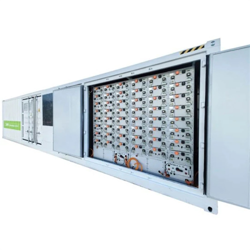
Schematic diagram of solar storage container (flat-plate collector).
The heat transfer fluid (HTF) was allowed to flow inside the serpentine pipe to discharge the heat by the PCMs. Fig. 1 shows a view for the solar storage container (flat-plate collector).

PARTICULATE DIAGRAMS_AR_Review_Student_2019
The sample in part a) is cooled to the point that the contents of the container are in the liquid phase only. Use the empty container below to draw what you believe the contents of the container will appear.
Exploring Chemical Solar Cells: A Comprehensive Analytical Guide
The evolution of chemical solar cells spans several generations, from the traditional crystalline silicon cells to advanced thin-film and emerging technologies like perovskite and organic solar cells. Each
Enhancing solar still productivity with organic phase change materials
Solar still systems often include organic phase change materials (PCMs) because of their remarkable thermophysical characteristics. Numerous innovative PCMs have been developed
Example draw.io diagrams and templates
You can create a wide variety of diagrams for many different industries using draw.io with our extensive template library and vast shape libraries. Open a diagram: Click on a diagram image on this page to
Related Contents
- Application research of new chemical solar container technology
- Distributed solar container application example design solution
- Doha solar container connector application diagram
- Zambia solar container connector application diagram
- Illustrated complete diagram of solar container system monitoring device
- Technical requirements for lead-acid solar container battery application
- Schematic diagram of solar container device on hydraulic station
- Solar container cabinet control system classification diagram
- Working principle diagram of tower solar container power station
- Application of thermal conductive materials in solar container
- Efficiency of chemical solar container system
- Preparation and application design of solar container materials